
BlocksCAD is a development environment that provides access to computer-aided design (CAD). It is based on Blockly, a software allowing an easy access to programming by a graphic assembly of blocks, like Scratch for example. This software is designed to be used by children as well as people with little knowledge of computers and programming. It is notably used by Einstein's Workshop, a workshop for children to promote technical skills.
In the footer of one project (Oct 2019), it says: “BlocksCAD is an education technology company dedicated to creating tools that help students of all ages pursue their love of science, technology, engineering, art, and math (STEAM). Our signature product, BlocksCAD, is a cloud-based 3D modeling tool that encourages users to learn math, computational thinking and coding concepts through visualization and designing models to be 3D printed”
BlocksCAD runs in the web browser with HTML 5. So it does not depend on Adobe Flash. However, on Google Chrome or Firefox, it requires the activation of WEbGL. BlocksCAD generates STL (StereoLythography) and XML files. The code can also be exported and used in OpenSCAD.
It was developed in the framework of the Einstein's Worskhop in the United States with the financial support of the DARPA (Defense Advanced Research Projects Agency). It is released as an open source project under GPL v3.
Currently, BlocksCAD is available in 11 different languages.
Beetle Blocks is a similar environment.
Initially, BlocksCAD was designed to teach computer science. In this sense, their [1] offers various resources both free and paid to promote learning in this area.
The Blockscad Youtube channel is a free resource with about 20 videos for all levels ranging from a "quick start" to "training videos" dealing with more complex features. The BlocksCAD community is also an important resource for learning by downloading projects and sharing information and questions through their forum.
BlocksCAD offers paid online courses, including BlocksCAD 101, specifically aimed at teachers wishing to learn in the field.
Finally, the platform also seeks to promote the teaching of programming by supporting institutions wishing to launch such a project. Thus, courses from 4 hours to 2 days, either face-to-face or online, are offered. These courses offer the possibility to acquire better personal knowledge as well as ideas for activities to be carried out with students. To go even further, BlocksCAD offers to implement their project in schools. This implementation includes instructor onboarding, lessons aligned to a common core, and a management dashboard for an initial fee of approximately $7.50 per student per year.
The BlockCAD interface is divided into four parts:
The block toolbar contains 11 groups of blocks, each represented by a different color. It is possible to divide them into three categories :
The workspace is located in the middle of the screen. To insert elements, simply click on the desired block and drag it into the workspace. At the bottom right, you have three buttons to manage the zoom and positioning of your project in the workspace.
The rendering window is used to visualize the objects created in the workspace. It is a system of orthonormal axes in which :
The three axes x, y and z intersect at the origin, i.e. the center of your rendering window defined by the following coordinate (0;0;0). When the line is dashed, it means that the coordinate is negative. There is no unit (cm, mm) because it is chosen at the time of printing.
The visualization does not work interactively, so it is necessary to press the "Generate rendering" button to visualize the changes. A small horizontal toolbar allows you to change colors (1), to make the axes appear and disappear (2), to zoom (3), to change the point of view (4) or to take a picture (5).
Finally, this is also the place where you can export your project in STL format by clicking on the "Generate STL" button
This menu is divided into two lines. The first one allows you to change the language (sphere), to download projects or to connect and save your account. The second line allows you to name your project and to navigate in your workspace. Note that the keyboard shortcut CTRL+Z to go back also works as it is possible to delete a block with the delete key of the keyboard.
On the right hand side, you can choose to display either "blocks" to view your elements in the workspace or "code" to have access to your code. However, this code cannot be modified.
To program a project, three different approaches are possible:
To start a project, go to the BlocksCAD editing page. You can also go to the main page and click on the orange "Create Now" button in the upper right corner.
This subchapter focuses on the basic functionality of combining blocks. To approach these notions, we will analyze different parts of a touch memory using the following notions
The "flower" described below was created to explore basic functionality. It took a few attempts to understand how to use loop variables (tip: check under "variables", then drag them).

The generated STL seemed to be error free and the printer happily started printing it:


Thanks to the Blockscad community, you have access to a gallery from which you can import projects, modify them and print them. This is an interesting solution to learn how to master more complex features.
As an example, we are going to set up a flower in order to adapt it to our desires. This flower uses the functions described in the previous chapter. Each arm is made of a cube which is moved on the x & y axis allowing to make waves and which is transformed with the check mark "hull" to create a unique arm.
To add a parameter, click on the brown block menu "variable" and insert a "set (. ) to" item at the top of the "subtraction" item. Add the variable by clicking on the arrow. Here you can choose the name of your variables. Then, add from the block menu "math" in blue the element allowing you to define your variable. You get variables (brown) defined by absolute numbers (blue)
The flower has 8 elements that can be defined.
The last step consists in inserting the variables in the place of each element defined before by an absolute number. You can then parameterize your flower by changing the variables in the brown elements at the top of your code. This way you get different flower models (code available under the images).
The next example shows how to use parameters, i.e. a user can change seven different parameters to create different shapes. See the comments in the exported OpenSCAD code below.
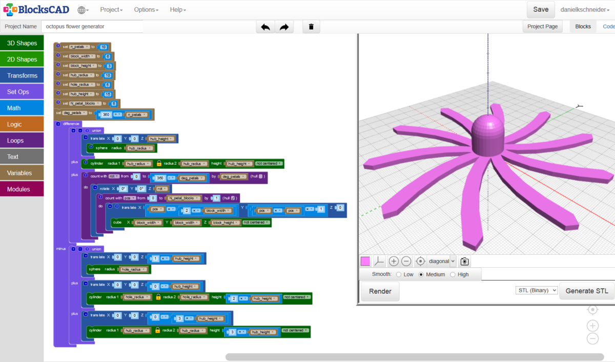
One generated example can seen in the following picture:

Generated OpenSCAD code:
//!OpenSCAD // Number of petals. A number between 2 and 15 maybe. n_petals = 8; // Building block of a petal. Each petal is defined as a string of block with a "hull" around it. block_width = 10; // Building block of a petal. Height should be anything that is printable, e.g. between 0.5 and 20. block_height = 2; // Radius of the hub. A good value is 10, i.e. a width of 2cm. hub_radius = 10; // Radius of the hole. 4-5 mm is about the size of a pen. Must be at least 1.5 smaller than radius. hole_radius = 5; // Height of the hub in the middle. Something between 5 and 30 ? hub_height = 15; // Petal length in terms of blocks. Try between 2 and 10. N_petal_blocks = 5; deg_petals = 360 / n_petals; difference() // Flower without the hole. It has a hub plus petals. union() translate([0, 0, hub_height]) // Sphere embedded on top of the hub sphere(r=hub_radius); > // The lower part of the hub cylinder(r1=hub_radius, r2=hub_radius, h=hub_height, center=false); // Loop to create N petals. Each one is rotated for (rot = [0 : abs(deg_petals) : 360 - deg_petals]) rotate([0, 0, rot]) // Untick hull for a postmodern experience. // chain hull for (pos = [0 : abs(1) : N_petal_blocks - 1]) hull() // This formula will create a curved line. You can try others. translate([(pos * (2 * block_width)), ((pos * pos) * 1), 0]) cube([block_width, block_width, block_height], center=false); > // This formula will create a curved line. You can try others. translate([((pos + 1) * (2 * block_width)), (((pos + 1) * (pos + 1)) * 1), 0]) cube([block_width, block_width, block_height], center=false); > > // end hull (in loop) > // end loop > > > // Three objects that will be subtracted to create the hole. One stick plus a ball on top. The cylinder at the bottom will shave off stuff that inhibits 3D printing. union() translate([0, 0, (1 * hub_height)]) sphere(r=hole_radius); > translate([0, 0, (0 - hub_height)]) cylinder(r1=hole_radius, r2=hole_radius, h=(2 * hub_height), center=false); > translate([0, 0, (0 - 3 * hub_height)]) cylinder(r1=hub_radius, r2=hub_radius, h=(3 * hub_height), center=false); > > >
In order to save your project on the platform, you are required to register. You can also download your project as an XML or STL file and save it directly on your computer. The STL file allows you to print your project directly with a 3D printer.
It is possible to export the project to OpenSCAD and work with the code. This solution is recommended for complex projects because working with the code becomes easier to realize the project in question. However, it is not possible to import an OpenSCAD project.
To go further in programming, tutorials are available.